Page 10 of 40

Re: Crofter985'S KLX650C supermoto build

Posted: Sat Feb 21, 2015 11:04 am
by Crofter985
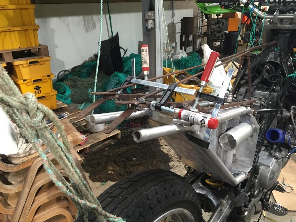
Right, the subframe needs a lot of work yet, plenum to finish, piping from turbo to plenum, a tray of some kind for the electrics, plumbing for the W/M set up aaand the W/M tank, which is where I thought I would start. I've been making bits up when I've had a chance over the last few weeks, little bosses and caps and screws for attaching all the plastics to the back of the bike. I had previously made up this jig which helped with getting some of the bits in the right place.
Image
Now I've been busy with work recently, and this last week I thought, right, a day off for the KLX, and when I got going I was just cracking on, kind forgot all about the photos till it was done, oops. What happened was...... I folded a bottom for the tank, welded it in, put on the back of the tank, a square, trimmed to size once on (the easy way, I'm no pro, ha!) put in a little flat bit at the back at the appropriate height to mount the attachment points for the rear plastics and the number plate, stoplight, etc.then a plate upstanding again to fill the space fully under the rear mudgaurd, then folded a top. I had found a vented filler neck on eBay , which was sitting around waiting for this job to be done.
Image
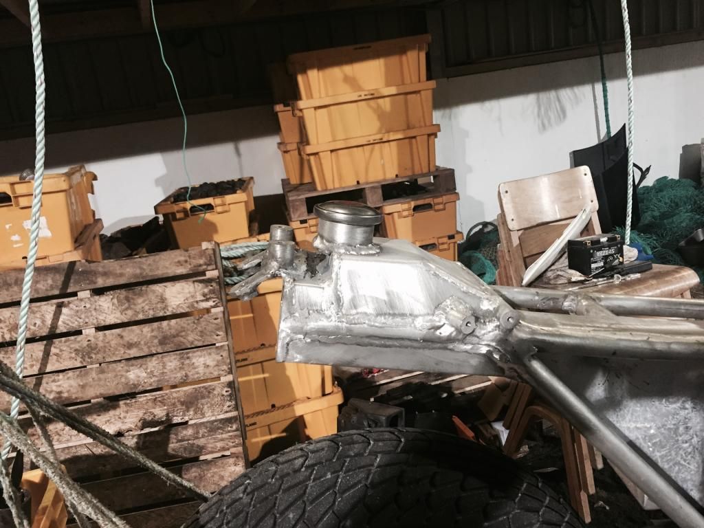
There it is, just a outlet boss to be welded in and a boss for a vent pipe.
And with it's clothes on.....
Image
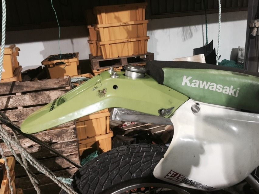
It was good to get this job done, another milestone!

Re: Crofter985'S KLX650C supermoto build

Posted: Sat Feb 21, 2015 9:09 pm
by Sandblaster
Jigs?
I just measure, cut, and pray.
Sometimes I even get lucky :-)
Everything seems to be coming right along.
And it all fits!
Nice job.

Re: Crofter985'S KLX650C supermoto build

Posted: Sat Feb 21, 2015 9:10 pm
by Sandblaster
Brute from kxriders says:

Very cool. It will be interesting to see how it works when it is done and set up.

Re: Crofter985'S KLX650C supermoto build

Posted: Sat Feb 21, 2015 9:17 pm
by Sandblaster
In regards to Hot Rods rods.
I would shy away from them if at all possible...
Most of the engine builders I have spoken to are saying that Hot Rods cranks are lasting 1/3 or less the time that the factory cranks are lasting.
The rods are suppose to be made in the USA but I know the cranks are coming out of China.
If they are using Chinese bearings, that would explain the poor performance.
I'll talk to Todd over at Pinsonnault Racing and see if he has a rod alternative for you.

Re: Crofter985'S KLX650C supermoto build

Posted: Sat Feb 21, 2015 10:31 pm
by Crofter985
Ok thanks mike, the info on hot rods is a bit of a blow.

Is this thread on KXriders too?

Re: Crofter985'S KLX650C supermoto build

Posted: Sat Feb 21, 2015 11:16 pm
by Sandblaster
Bits of it are.
I've got some of your pics there as well as some of your info.
I have links to the postings here.
Right now their site is having problems or I'd post a link to it.

Re: Crofter985'S KLX650C supermoto build

Posted: Sun Feb 22, 2015 12:17 am
by Sandblaster
Here's a link to the thread at KXriders..

http://www.kxriders.com/forums/index.ph ... 683.0.html

Re: Crofter985'S KLX650C supermoto build

Posted: Sun Feb 22, 2015 12:24 am
by Sandblaster
Here's a link to the supermotojunkie thread.

http://supermotojunkie.com/showthread.p ... -Supermoto

It has a lot of really good details...

Re: Crofter985'S KLX650C supermoto build

Posted: Sun Feb 22, 2015 4:05 am
by Crofter985
That's a good site.

Re: Crofter985'S KLX650C supermoto build

Posted: Sun Feb 22, 2015 2:09 pm
by Crofter985
There's still a bit to go with the plenum. So next I started on a access door for getting to the W/M jet to change it or maintain it, there is three sizes of jet with the kit and the body that the jet is screwed into has a little bronze filter in it that might need looked at at any time. I got a length of 25x12mm aluminium bar to make a frame, mitred it then vee'ed it out at each join so I could get good penetration with the welder then clamped it to a bit of 6mm plate so it would be flat, and tacked it up, turned it , welded it from the other side. Then back to the first side and filled the gap completely with weld.
Image
This was kinda like the tank job, I was on a mission and I really should have been at work so I was trying to get on. So not a lot of pics.
When all the joins were filled proud, I ground them back flush with the rest of the bar frame. I then cut a lid to go over the frame and marked it out for drilling holes for bolts to seal it. There will be a rubber gasket made to fit the lid/frame. I drilled all the holes out then started tapping them all to M8.
Image
That's not too bad, a bit hefty but it will be easier to seal if it's chunkier.
Next I wanted to have a go at air inlet to the plenum from the turbo. I've looked at this a lot, I've really not been able to decide, inside or outside of the frame rail for the inlet pipe. Inside would be tight and fiddley but really neat if I made a good job of it. Outside would be sticking into my leg. So as I was looking at the access door for the W/M jet I thought, well that sticks out a bit now, another bit of pipe there mightn't hurt? So I'm going to give going outside a bash. Now I did not want to go around the frame rail with a circular section, oval would be better if it does indeed stick into my leg. I was also aware that if you squash a pipe out of round you steadily reduce the actual cross sectional area of the pipe till flat, so simply squashing the pipe wasn't going to do. The pipe coming out of the turbo is 50mm O/D and o have a bit of 32mm O/D pipe that looks like it would do for the sides of the oval. So I'm going from 50mm to 32mm, and I want to do that in the space of 60-70mm and I want it to be as neat and non restrictive as possible. I decided to try folding or shaping plate into a cone. So, make a bender, like this.....
Image
I took the jaws out of the vice and drilled plates for the ends then just zipped a few bits of flatbar together and put a v profile on the other side.
It works a treat! I drew out expanded views of what I wanted to bend up and with lots of lines drawn on for guides, it turned out not bad.
Image
So that was going from 50 to 32mm, I did figure this all out in O/D but it will surely be close to actual, to get the same cross sectional area I need to space off the two sides of the 32mm pipe by 36mm each side, so I made it 40mm because there is more surface area presented to the air at that so a little extra area will give it an easier time, see, I really want as much air in this engine as possible!!!!!
So I cut some bits of plate for the sides and tacked it together then welded it up.
Image
And from the end.
Image
Now I sliced it in half on the saw at an angle turned it around to make a bend and made a couple of slits in it to point it around into the plenum.
Image
And from above.
Image
That's as far as I can get with that for now, I've run out of bands for my power file, I can't clean up the inside of that tube very well without them. So more of that later.