
Building your own Dyno
-
Crofter985

- Posts: 240
- Joined: Mon Nov 10, 2014 6:47 pm
- Location: Shetland Islands, UK
Re: Building your own Dyno
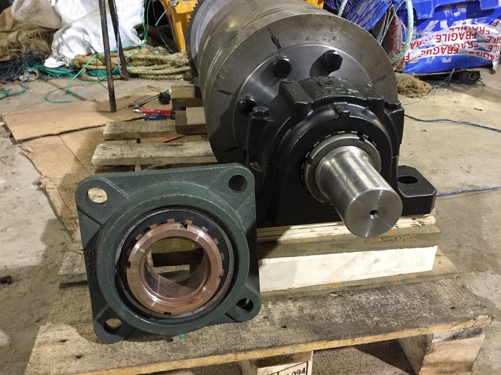
This is the bearing that wouldn't do, it's not so inferior looking but waaaay behind in spec.
-
Crofter985
- Posts: 240
- Joined: Mon Nov 10, 2014 6:47 pm
- Location: Shetland Islands, UK
Re: Building your own Dyno
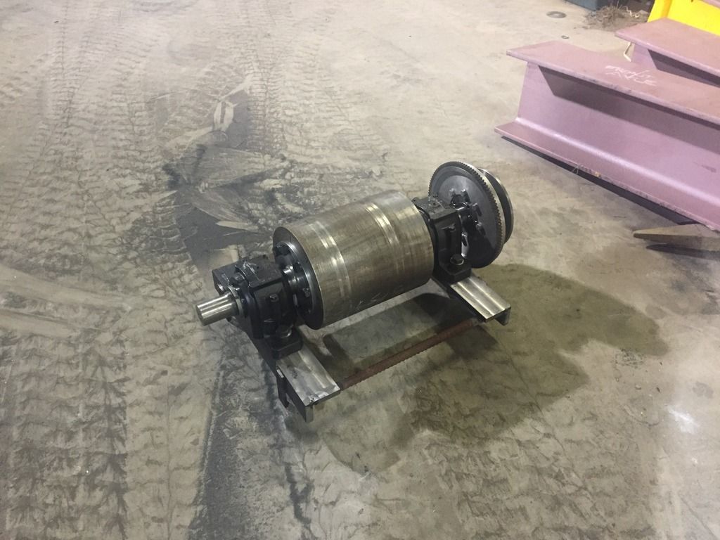
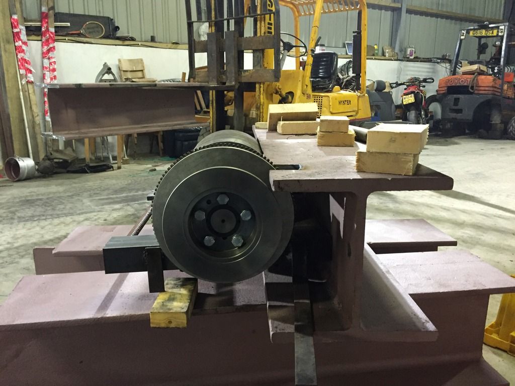
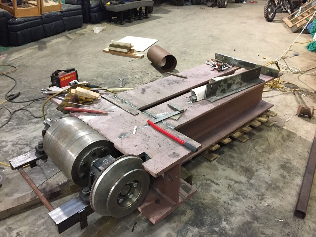
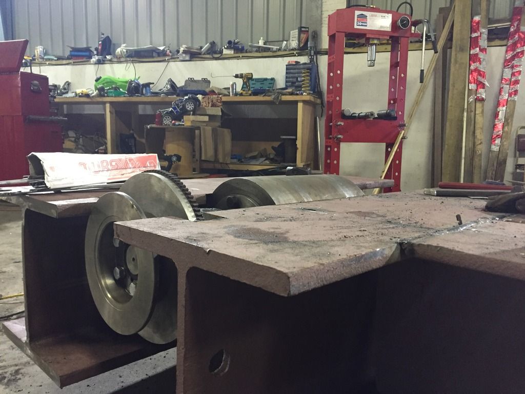
This is where I'm going, two beams forming the main chassis with a cross piece welded on then the roller mounted on that and another cross piece behind. The roller is pictured behind both cross pieces but will live between the two. One of the reasons for it contained between the two is if there is ever a bearing failure or the roller breaks free the beams will stop the roller going into orbit.
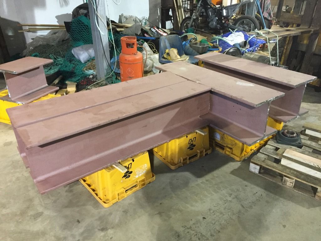
Again in this next view the roller will be between the cross beams not behind, I plan some sort of adjustable front wheel retainer that will slide fore and aft between the two main beams.
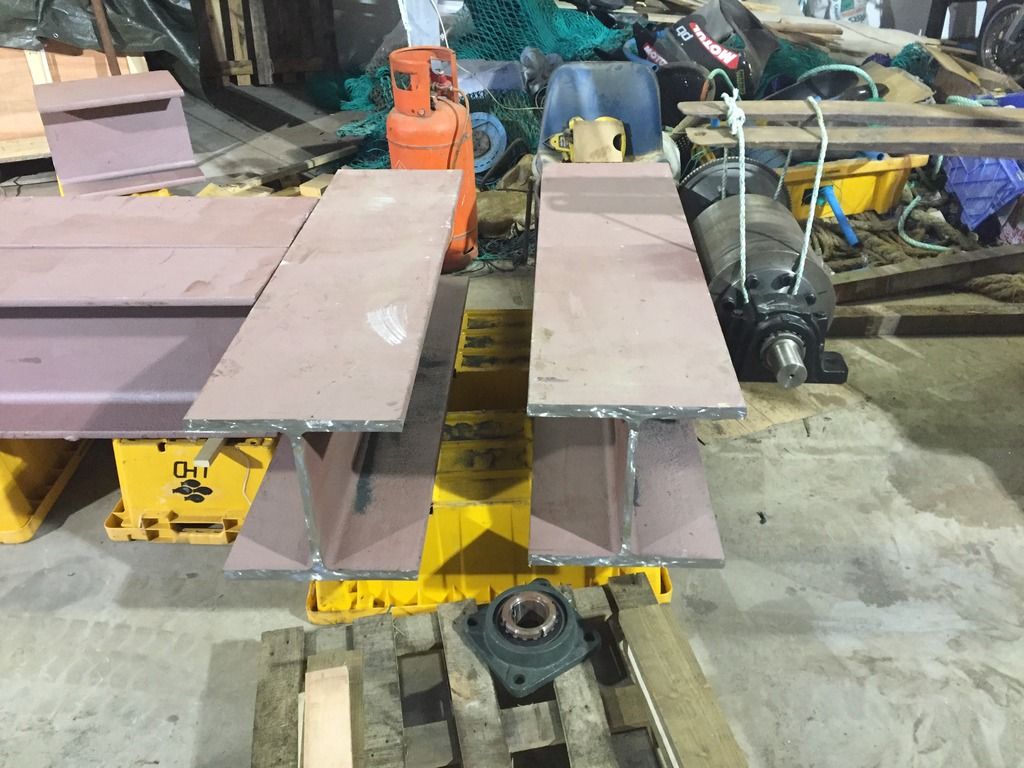
The cross beams are offset, that is to leave me with a platform to put an outrigger bearing so I can put a second shaft to hook up directly to the countershaft, this would be good right now, to get good consistent conditions to test without the variable of tyre slip. For now though, it will be tyre to roller to deliver the power to the roller.

-
Sandblaster

- Posts: 6320
- Joined: Thu Jun 07, 2012 3:50 pm
- Location: Eugene, OR
- Contact:
Re: Building your own Dyno
Oh yeah, those pillow block bearings you are using are the same type we used in the Wood products industry for HUGE Chippers, edgers, and planers. If they are maintained they will last you a life time in your application.
Fore and Aft? Is that what you get when you ride big bikes? You start raising the Mizzenmast and storing your tools in the Afterhold?
If so I want to get a big bike too
Fore and Aft? Is that what you get when you ride big bikes? You start raising the Mizzenmast and storing your tools in the Afterhold?
If so I want to get a big bike too
If bikes are for kids I'll never grow up.
-
Crofter985
- Posts: 240
- Joined: Mon Nov 10, 2014 6:47 pm
- Location: Shetland Islands, UK
Re: Building your own Dyno
Yeh, fore and aft, ha ha. My life at sea always filters down to everything.
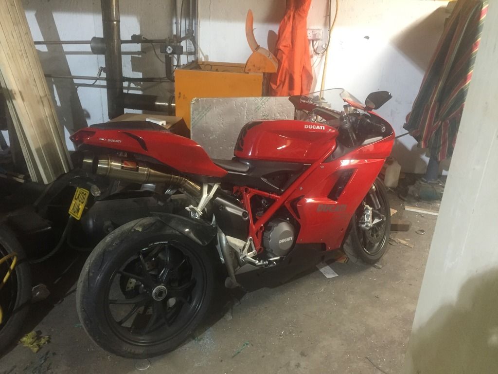
Guess you saw my signatures thing o supermoto junkie. I bought a Ducati 848 a few weeks ago, a guy was selling it around where I was away working, it's a bit of a backwater so I got it cheap, too good to pass up. High miles but a nice solid bike.
I sold one of my XRs to make way for it.
The Ducati is bonkers, I had a run out with it, just to town and back. Very nice.
I was lucky I got a dryish day. Not so lucky yesterday. My van was in town and I had just burned out my 9" grinder cutting the "H" beams, so I took my remaining XR to town. 4 miles in wind got up and started laying down wet snow, 20 miles to go. Sliding and spinning all the way. Well what do you know, winter is here!!!!!!
-
Crofter985
- Posts: 240
- Joined: Mon Nov 10, 2014 6:47 pm
- Location: Shetland Islands, UK
Re: Building your own Dyno
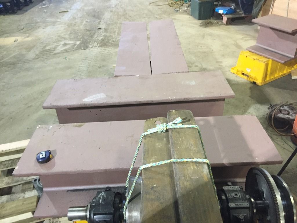
Got on with flatning the beds for the bearings, the bed is just two bits of 20x75mm flatbar welded together. 100x20 would have been better or 150x20 but it's all I could get.
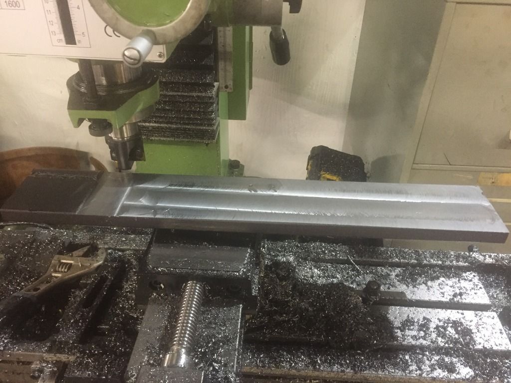
That washers are 25mm thick, just to get longer bolts in to use the bolts elasticity.
There is also a bit of bored bar at the bottom, 50mm and the bar, say 16mm after machining, the bearing is 32mm and the washer is 25mm. Bolts are 150mm so plenty of room for the nylock.
Then that dyno testing device.

That washers are 25mm thick, just to get longer bolts in to use the bolts elasticity.

There is also a bit of bored bar at the bottom, 50mm and the bar, say 16mm after machining, the bearing is 32mm and the washer is 25mm. Bolts are 150mm so plenty of room for the nylock.

Then that dyno testing device.

-
Sandblaster
- Posts: 6320
- Joined: Thu Jun 07, 2012 3:50 pm
- Location: Eugene, OR
- Contact:
Re: Building your own Dyno
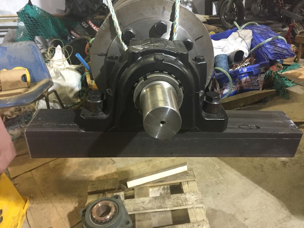
That is one heavy duty dyno....
And you have a beautiful test unit...
Nice find.
My Dad has a Aprilia 1000 V twin something or other.
I'll be taking it for a spin when the weather gets better.
Here is what happened when my kid brother took it out
https://www.youtube.com/channel/UCOFlR6 ... 2yA/videos
I hope to see some similar video's when your weather clears up
If bikes are for kids I'll never grow up.
-
Crofter985
- Posts: 240
- Joined: Mon Nov 10, 2014 6:47 pm
- Location: Shetland Islands, UK
Re: Building your own Dyno
Ha ha, if the shit weather goes on as long as usual the KLX will be finished by the time it betters up. Well running, as discussed before it will possibly never be finished, in a constant state of flux.
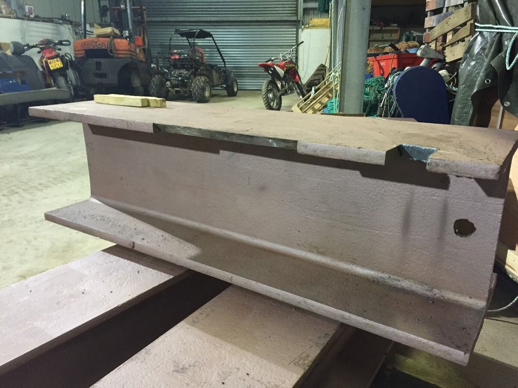
Not a lot of obvious progress but one of the jobs done was chamfering the edge of the H beam in way of the roller.
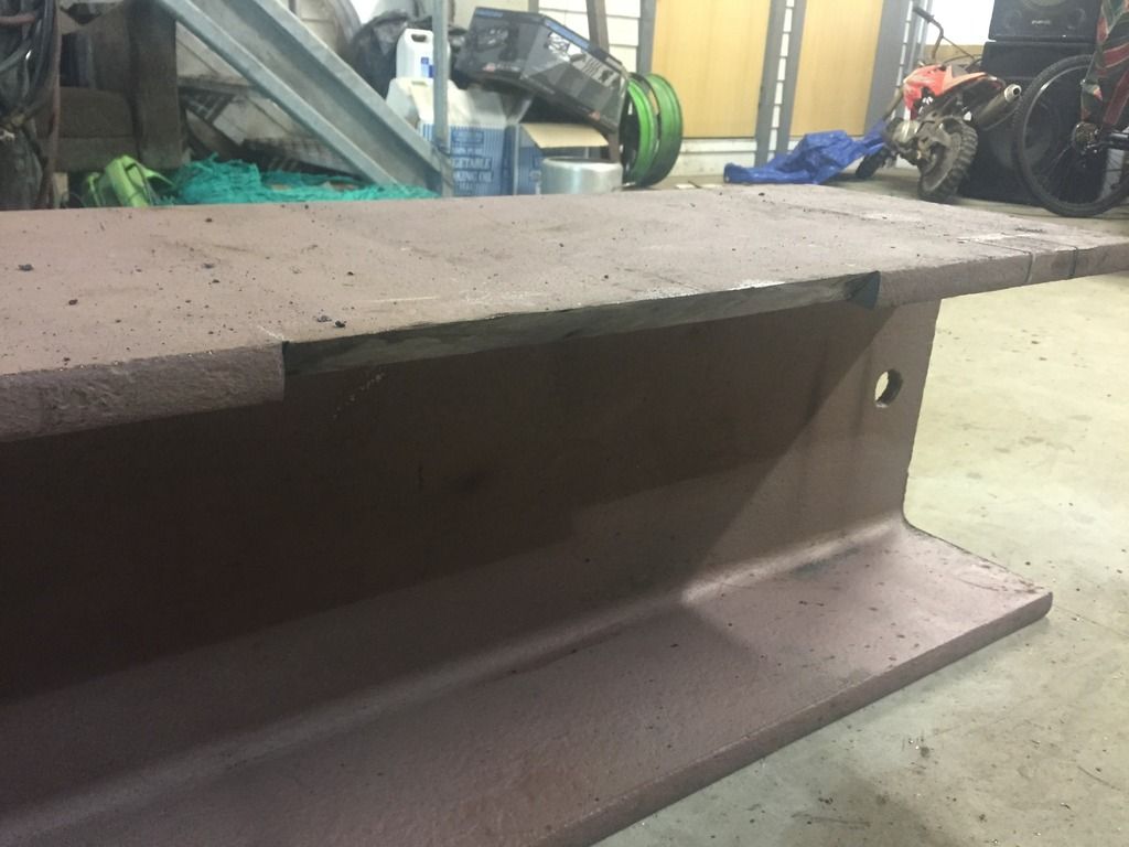
I finished the roller chassis, it's got legs as well which should hold it at the right height or near enough to shim to the correct height. A little adjusting and checking for squareness in the morning and I should be ready to offer the roller up to the beam.

-
Sandblaster
- Posts: 6320
- Joined: Thu Jun 07, 2012 3:50 pm
- Location: Eugene, OR
- Contact:
Re: Building your own Dyno
You know, when you first started talking about building a dyno I thought it might be a pie in the sky idea...
I am so glad you are following through and doing such a great job.
I hope it inspires others to do their own...
I am now on the A list for a local dyno so I will be doing many tests in the near future
I am so glad you are following through and doing such a great job.
I hope it inspires others to do their own...
I am now on the A list for a local dyno so I will be doing many tests in the near future
If bikes are for kids I'll never grow up.
-
Crofter985
- Posts: 240
- Joined: Mon Nov 10, 2014 6:47 pm
- Location: Shetland Islands, UK
Re: Building your own Dyno
Chunk out for starter ring.
Roller chassis slid in.
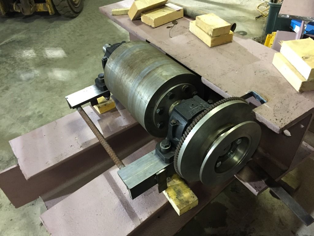
Second beam slid in.
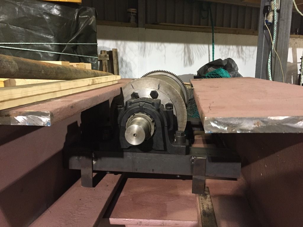
When I got the roller in with the legs on the beam the roller and chassis was quite low. So I ended up spacing it up 18mm with a few blocks of mdf did all the root passes. The root passes are all 3.2mm MMA rod with the little inverter welder at full power 140A. You will also notice I have had to put a 15mm spacer in at the beam/chassis join. This gap became bigger as I moved the chassis up.
Then finish welding with 4mm rods to lay on a bit of meat.

Roller chassis slid in.


Second beam slid in.

When I got the roller in with the legs on the beam the roller and chassis was quite low. So I ended up spacing it up 18mm with a few blocks of mdf did all the root passes. The root passes are all 3.2mm MMA rod with the little inverter welder at full power 140A. You will also notice I have had to put a 15mm spacer in at the beam/chassis join. This gap became bigger as I moved the chassis up.

Then finish welding with 4mm rods to lay on a bit of meat.

-
Crofter985
- Posts: 240
- Joined: Mon Nov 10, 2014 6:47 pm
- Location: Shetland Islands, UK
Re: Building your own Dyno
yesterday afternoon and evening was a lot of doing for not much result. I welded the two beams that will form the main fore aft spine of the chassis on to the cross beam. Poorly, it would seem it did not look right, I was thinking all the time, " shit these beams are twisted", no, they were on twisted. So I cut them off again. Another go, that did not go good either. Off they came again. Third time it was ok. I was just in too much of a hurry, if I had been standing back every now and then instead of forging blindly on I might have got it first go but whatever it's on now and straight.
It's quite an eye opener how much these beams twist around when you are welding them. I used a bit of 1.5mm sheet to gauge the gap at the roller, by the time I had welded the roller chassis to the cross beam the gap had closed right up and the beam was jamming the roller, but there was welding on the other side to do so I was thinking it would probably be able to pull it the other way. Sure enough the gap is about 0.5 mm again now and I've only just started welding the other two beams on.

You can see in the picture above the roller chassis just has a bit of reinforcing bar across it, that's because those chassis legs were made too long so they could be cut to size. The 2nd cross beam was offered up to it then the beam was marked where the chassis legs would touch it and the chassis legs were marked where they would be cut.
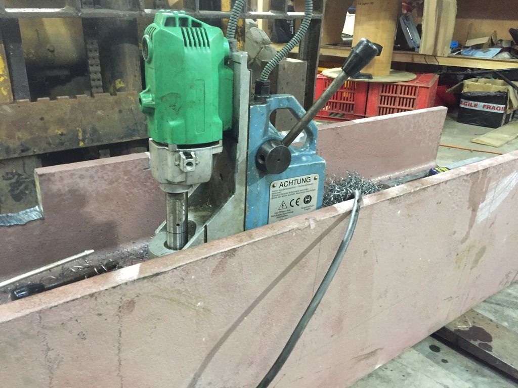
Next I got the bit of bar I would use for the end of the roller chassis and put it on the beam and tacked it to the beam as per the chalk marks. Then I got out a extremely cool tool, a magnetic base drill. I got a loan of it from a friend who has a engineering business. 4x 20mm holes coming right up, sir! That thing cuts holes so easy!!
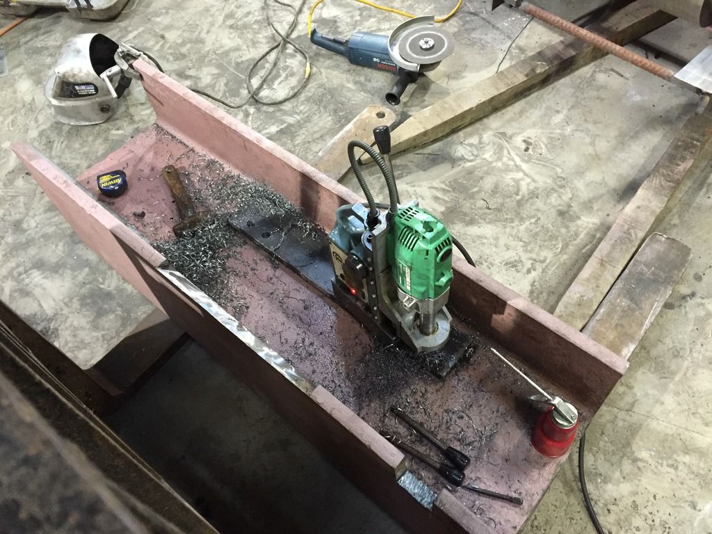
Achtung, indeed!
The I put it back on with the bar bolted to the beam and tacked it in place. Took the beam off and put a bit more weld on but not to a finish. Got to go back to work now, I thought I was going to get a test pull this week but no, ah well, soon though.
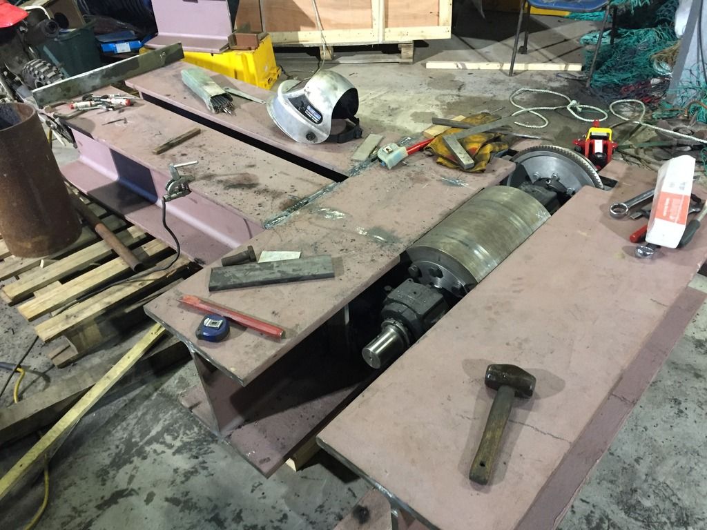
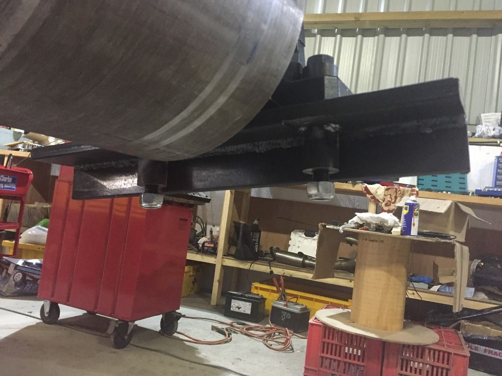
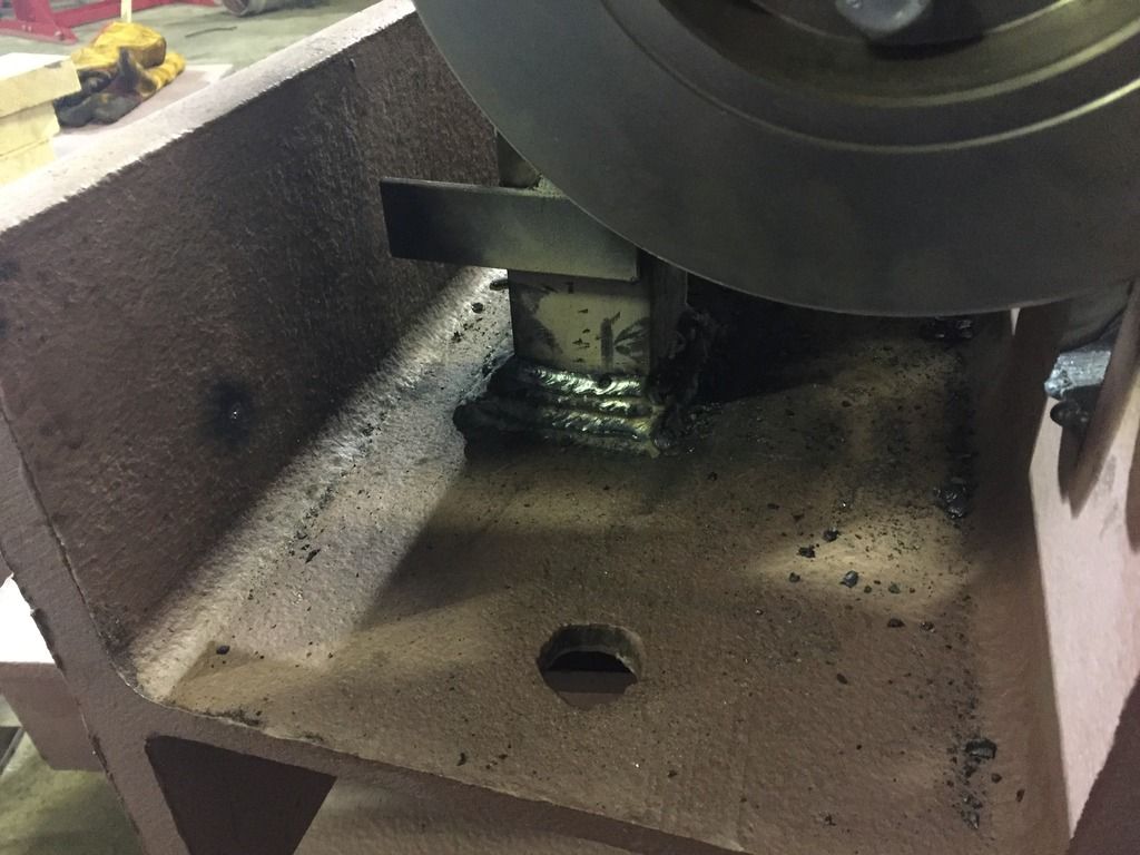
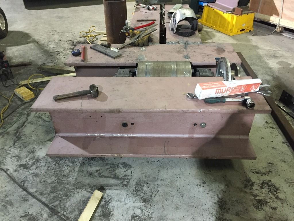
This pic shows how far the roller sticks up from the chassis.
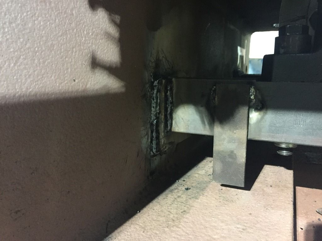
And this one shows the bolts holding the beam on the end. The other two holes are for locating pins to make fitting the beam easier. I'm only away for a few days then I'll be back at it again. Still need to fit the starter, the brake caliper, the front wheel stay( which will be adjustable up and down between two main chassis beams), fit the speed sensor and finish off the welding.

It's quite an eye opener how much these beams twist around when you are welding them. I used a bit of 1.5mm sheet to gauge the gap at the roller, by the time I had welded the roller chassis to the cross beam the gap had closed right up and the beam was jamming the roller, but there was welding on the other side to do so I was thinking it would probably be able to pull it the other way. Sure enough the gap is about 0.5 mm again now and I've only just started welding the other two beams on.

You can see in the picture above the roller chassis just has a bit of reinforcing bar across it, that's because those chassis legs were made too long so they could be cut to size. The 2nd cross beam was offered up to it then the beam was marked where the chassis legs would touch it and the chassis legs were marked where they would be cut.
Next I got the bit of bar I would use for the end of the roller chassis and put it on the beam and tacked it to the beam as per the chalk marks. Then I got out a extremely cool tool, a magnetic base drill. I got a loan of it from a friend who has a engineering business. 4x 20mm holes coming right up, sir! That thing cuts holes so easy!!

Achtung, indeed!

The I put it back on with the bar bolted to the beam and tacked it in place. Took the beam off and put a bit more weld on but not to a finish. Got to go back to work now, I thought I was going to get a test pull this week but no, ah well, soon though.

This pic shows how far the roller sticks up from the chassis.

And this one shows the bolts holding the beam on the end. The other two holes are for locating pins to make fitting the beam easier. I'm only away for a few days then I'll be back at it again. Still need to fit the starter, the brake caliper, the front wheel stay( which will be adjustable up and down between two main chassis beams), fit the speed sensor and finish off the welding.
