Another thing I was concerned about was the tube coming from the turbo pulling one way or the other when welding, alloy is a pain, it distorts a lot when welding and it's certainly something to keep in mind. So I made a little gusset out of plate and folded a flat on the edge. It helped the stiffness and I hope it helps keep everything in place.
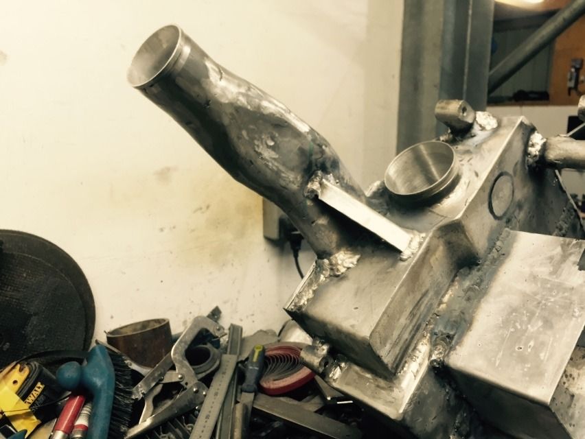
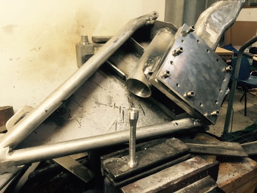
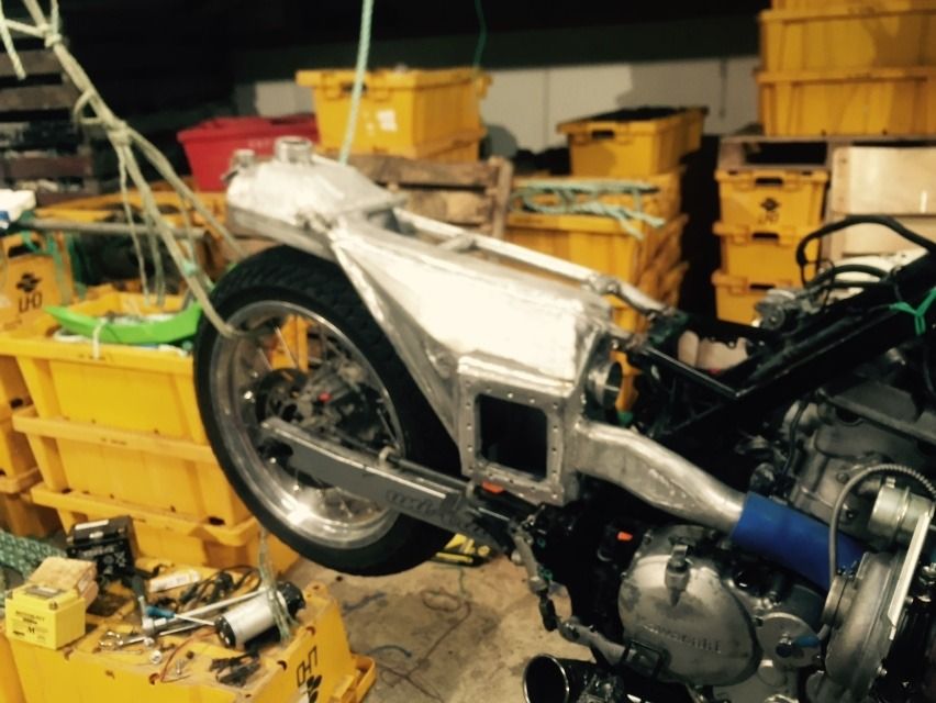
Then on went the W/M jet access door, with a little tab down to the induction tube just to add a little more strength to it all, also on this subject was the side-panel attachment point, I thought it would be good to extend this through the plenum to the other side to add stiffness to the structure. There will be a bit of force on the sides of this plenum. If I can get up to 15psi boost, it will be over 1000lbs(450kg ish) on the square area of each side of the plenum, thankfully of course it's distributed evenly over the whole side and not on any one point. Also this is going to be in the way of the end of the induction tube, so I waisted it but left a base on the end so I could get a generous blob of weld on it.
Then the application of a blob of weld, BZZZZZZZZZZZZT, ok another one BZZZZZZZZZZT
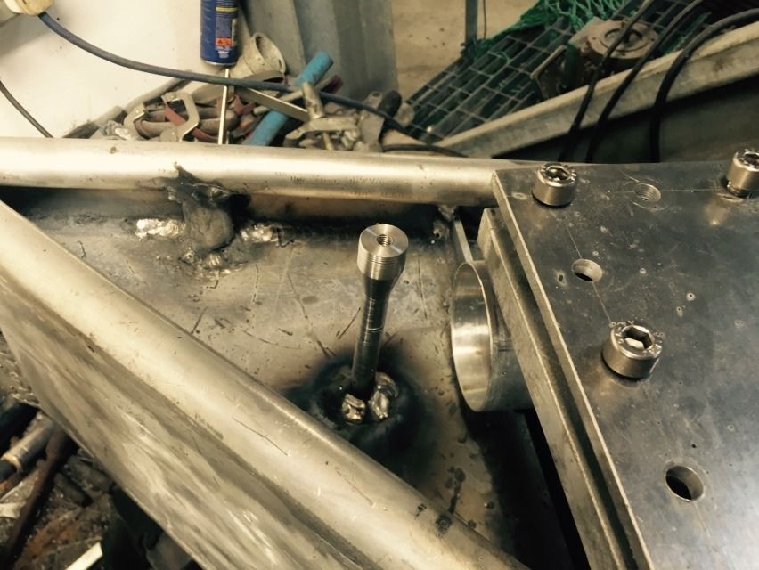
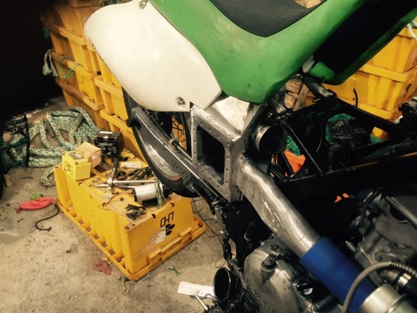
Next up I cut out a bit of plate that would more than cover the side and started to trim and fold it to shape pausing only to fillet my thumb, the saw kicked back and pushed a sharp edge of alloy at me, quickly, it wasn't the slightest bit sore, strange. It was a tricky job that needed a bit of time to get right, or near enough right to do, when I got as near as I could to right, on with the alloy glue! I have continued to adjust this welder as I go and it's going good again now. Even this 2mm plate, you can have a butt join with a gap and still weld it nicely without it blowing holes everywhere or sitting on top like bird sh!t. In this next photo you can see the folds and the end of the bar for the sidepanel attachment bolt.
And another view.
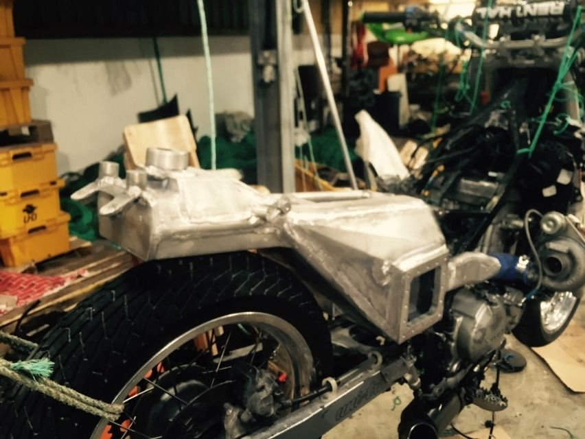
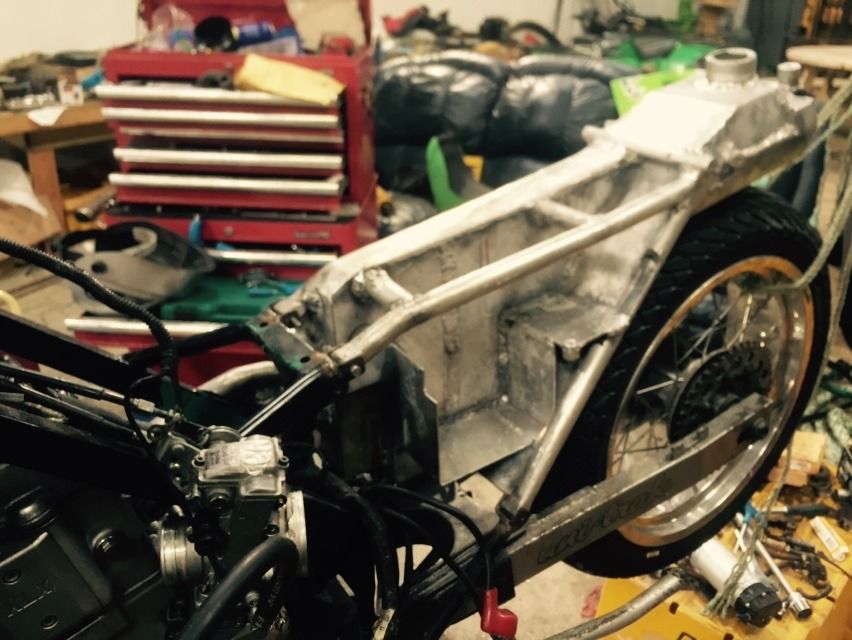
And with some clothes on.
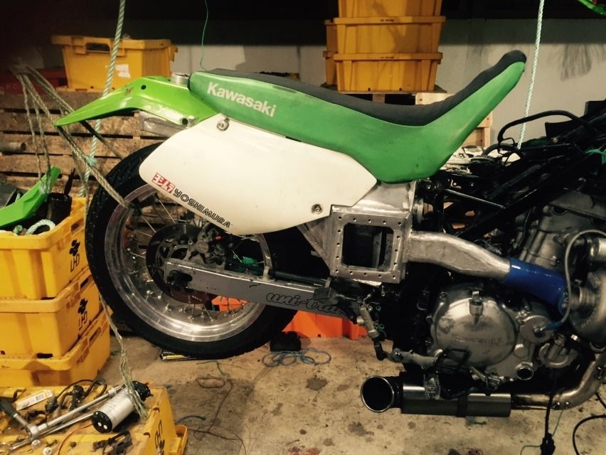
Now there's a mistake, I sized that door to clear the access door then as I went along I thought it best to move the door further to the rear, I forgot about the sidepanel then becoming a problem.
So there it is for now.
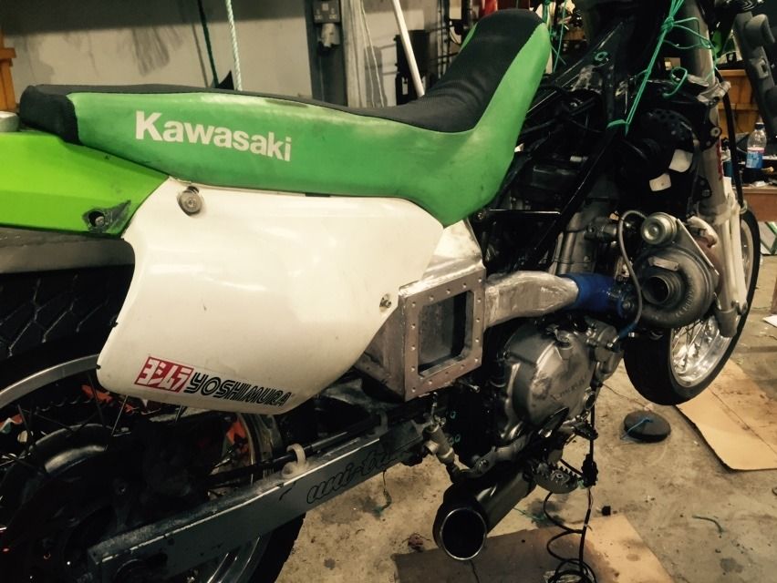
Still loads to be done. The left hand side of the subframe has a bit of work to finish it off. And the piping for the W/M system, I am going to try to make a system for that so the pump cannot suck a air bubble. If I'm relying on a water pump to keep the engine from melting I better let it do it's job. I will make a small reservoir at the bottom of the plenum to trap the bubbles and put them back to the tank.
Yet another thing that's been in my thoughts is the carb, I have notched the frame a little around the shock mount but it still looked a tortured route for the air entering the carb, the carb sits in the wrong place. I am thinking the solution is to make a different attachment for the carb to the engine, do away with the carb rubber mount, and make a alloy one, matched to the carb mounting spigot and attach them both with a bit of rubber hose and two clips. The carb could then be mounted flatter and slightly kinked to the right hand side. But as usual there will be no hard copy plan for that and it remains to be seen how it might turn out. IF.... I had thought about this before I went with the idea of lifting the tank, seat and bodywork 15mm I might have seen this was not needed, OH WELL, never mind.
BTW, I will weld up that notches in the frame before completion. I think I will also put the wossner forged piston in and the KLX "R" intake cam I have and also I have a Carrillo rod on order too, 6-7weeks and that will be here. So for all that the engine will be out of the frame. You never know I might even paint it!!!!
If anyone wants to click on this it's at their own peril. It's my thumb post accident. Enjoy.
http://i1243.photobucket.com/albums/gg5 ... k3spsw.jpg


